








RED sensor installation
Install the RED sensor on your own
Everything connects inside the electrical cabinet, with equipment your electricians already know: DIN rail, screw terminals and bayonet-type current clamps. For all your motors: direct-on-line start, star-delta, soft starter or variable frequency drive.
VIDEO TUTORIAL
The installation on video
RED sensor installation tutorial — video in English
BENEFITS
An installation designed for speed
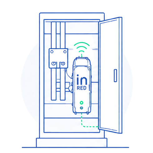
Quick to deploy
DIN rail, screw terminals and bayonet-type current clamps: equipment your electricians already know
15 to 25 minutes per sensor on average
A single gateway for up to 50 RED sensors
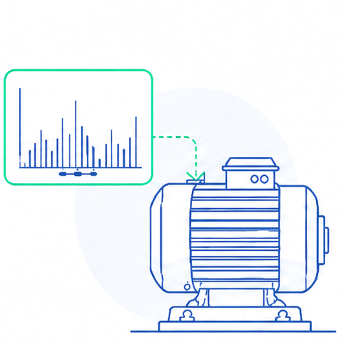
No intervention on the machine
No sensor to attach to the machine
Bayonet-type current clamps: cables are not cut
Low- or medium-voltage motors

Autonomous and supported
Can be done by your electrical team or a contractor
Step-by-step guide, video and one-pagers
Insens support if in doubt
Compatible with all your starting methods
Motor direct-on-line, star-delta, behind a soft starter or a variable frequency drive: RED connects at the same place, on the motor side.
THE 6 STEPS
From DIN rail to commissioning
1
Prepare and check the equipment
Circuit de-energized, absence of voltage verified. Each sensor is assigned to a machine: check its serial number (EUI) and the clamps intended for it.
2
Mount the sensor on the DIN rail
In the cabinet, close to the motor’s phase cables: the clamps’ RJ45 cable is 2 m (6.6 ft) as standard, 5 m (16 ft) or 10 m (33 ft) on request. The DIN rail must be earthed.
3
Fit the current clamps
Bayonet-type current clamps, fitted directly on the motor cables, even with the machine running: nothing is cut. Arrow pointing toward the motor. Then connect the blue RJ45 cable to the sensor.
4
Connect the voltage
One DIN-rail fuse holder and one wire per phase, between the feed-through terminal block (or the drive output) and the voltage terminals under the sensor. Voltage no. 1 on the phase of clamp no. 1.
5
Power the sensor
A 24 V DC supply, plugged into the green connector above the sensor, observing polarity. No 24 V DC available? A DIN-rail 230 V / 24 V converter does the job.
6
Connect the gateway and check
Screw on the three antennas, power up, then check the LEDs. Sensor LED 2: connected to the gateway, even with the motor stopped. LED 1: installation correct, motor running.
LOW AND MEDIUM VOLTAGE
RED monitors low and medium voltage alike
LOW VOLTAGE
In the cabinet, at the motor feeder
Voltage is taken through fuse holders, between the feed-through terminal block (or the drive output) and the sensor. Bayonet-type current clamps fit directly on the motor cables.
5 clamp ratings, up to 1,000 A
Beyond that: flexible Rogowski coils supplied by Insens
Direct-on-line, star-delta, soft starter or drive
MEDIUM VOLTAGE
On the secondary of the current transformer
No intervention on the medium-voltage circuit: the clamps are fitted on the secondary of the current transformer, i.e. on the low-voltage side. Both current and voltage are measured on that side.
Prerequisite: a transformer down to low voltage
Clamps on the (low-voltage) secondary of the current transformer
Same sensor, same gateway, same LEDs
A clamp suited to every current
Five ratings of bayonet-type current clamps cover up to 1,000 A; beyond that, a flexible Rogowski-type coil is used.
Documentation
Download the installation documentation
The one-pagers summarize the connection and checks on a single page, to keep at hand during the job. The datasheet details the characteristics of the RED 03 sensor. Documents available in English.
Installation one-pager — low voltage
Wiring diagram, steps and checks for an asynchronous motor. PDF · EN
Installation one-pager — medium voltage
Connection on the secondary of existing measurement transformers. PDF · EN
RED 03 datasheet
Technical characteristics and compliance of the sensor. PDF · EN
Receive the documentation
Enter your details: the document you choose opens in a new tab.